I have a well-functioning UPS with a faulty network interface, I use it for the iobroker server. The problem was that it did not shut down the PC in the event of a prolonged power outage.
These may require:
Programmer USB to ESP-01 Adapter ESP8266
FT232RL FTDI USB to TTL Serial Converter 3.3V 5.5V
Resistor Kit Assortment, 0 Ohm-1M Ohm
LM2596 DC-DC Step Down Variable Volt Regulator
AC DC Power Supply Buck Converter Step Down Module
To smarter the UPS, I made the following circuit using ESP8266 and PCF8591 and built it into the UPS.

Attention!
MAINS VOLTAGE DOES NOT PLAY, DEADLY ELECTRIC SHOCK, MAY CAUSE FIRE! ONLY AT YOUR OWN RESPONSIBILITY AND ONLY IF YOU KNOW WHAT YOU ARE DOING!
Before disassembling the UPS, turn it off and unplug it. After removing the cover, disconnect the battery immediately!
Power is supplied from the internal battery, so it stays functional even in the event of a power failure. With the help of the PCF8591 A / D converter we can measure the battery voltage via a voltage divider made of 2 resistors. PCF8591 is connected to ESP8266-01 on the I2C bus as shown above (green wire SDA is GPIO0 and yellow wire SCL is GPIO2). Remember the 4.7K pull-up resistors. This completes first part of the circuit.
In the next step, the presence of mains voltage is examined. Connect a 230V-5V StepDown power supply module (eg HI-Link HLK-PM01) to the UPS input cable. The output is connected to the ESP8266 via an optocoupler, so this part is also galvanically isolated. The optocoupler can be, for example, PC817, TPL621, etc. With 470 Ohm resistor at its input. Connect its output to the ESP8266-01 RX pin, this will now be used as input. This input is connected with a 1K resistor to the 3.3V supply voltage.
Place it inside the UPS after programming the ESP8266. The circuit is not large, we will find a place for it.
Enter the information required to connect: SSID, Password and ioBroker IP address, then upload the code.
/****************************************************************
  *   https://myhomethings.eu
  *   Generic ESP8266 module
  *   Flash size: 1M (no SPIFFS)
/****************************************************************/

#include <ESP8266WiFi.h>
#include <PubSubClient.h>
#include <Wire.h>

const char* ssid = "SSID";
const char* password = "Password";
const char* mqtt_server = "192.168.x.xxx";

int PCF8591 = 0x48;
float ain0;
String battery_voltage;
char battery_msg[25];
unsigned long last_msg = 0;
unsigned long msg_freq = 5000;
int mqtt_flag = 0;
int network_voltage_pin = 3;

WiFiClient espClient;
PubSubClient client(espClient);

void setup_wifi()
{
  delay(100);
  WiFi.mode(WIFI_STA);
  WiFi.begin(ssid, password);

  while(WiFi.status() != WL_CONNECTED)
  {
    delay(500);
  }
  randomSeed(micros());
}

void reconnect()
{
  while(!client.connected())
  {
    String clientId = "ESP8266_UPS";
    if (client.connect(clientId.c_str()))
    {
      // pass
    }
    else
    {
      delay(6000);
    }
  }
}

void setup()
{
  Wire.pins(0, 2);
  Wire.begin(0, 2);
  setup_wifi();
  client.setServer(mqtt_server, 1883);
  pinMode(network_voltage_pin, INPUT);
}

void loop()
{
  if (!client.connected())
  {
    reconnect();
  }
  client.loop();

  if(digitalRead(network_voltage_pin) == HIGH && mqtt_flag == 0)
  {
    client.publish("UPS/Network_voltage", "false");
    msg_freq = 5000;
    mqtt_flag = 1;
  }
  if(digitalRead(network_voltage_pin) == LOW && mqtt_flag == 1)
  {
    client.publish("UPS/Network_voltage", "true");
    msg_freq = 30000;
    mqtt_flag = 0;
  }

  unsigned long Millis = millis();
  if (Millis - last_msg > msg_freq)
  {
    last_msg = Millis;
    Wire.beginTransmission(PCF8591);
    Wire.write(0x04);
    Wire.endTransmission();
    Wire.requestFrom(PCF8591, 2);
    ain0 = Wire.read();
    ain0 = Wire.read();
    ain0 = ain0 * (13.73 / 255);
    battery_voltage = String(ain0);
    battery_voltage.toCharArray(battery_msg, 25);
    client.publish("UPS/battery_voltage", battery_msg);
  }
}
When the assembly is complete, plug in to the power and turn it on. After 30 seconds, the data will appear in ioBroker.
Now we know if there is power in the machine and what is the battery voltage.
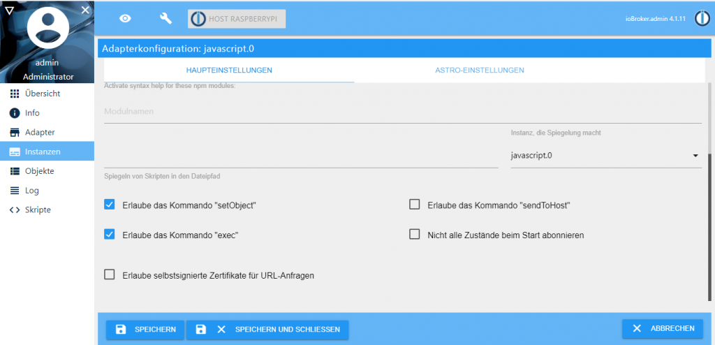
Go to ioBroker, select javascript.0 on the Instances tab to configure the adapter and allow the ‘setObject’ and ‘exec’ commands to run.
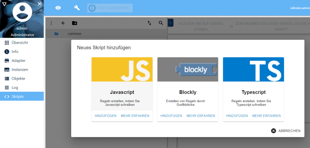
Click the Script tab and create a new Javascript.
Copy the following code:
on({id: 'mqtt.0.UPS.battery_voltage'/*battery voltage*/}, function (obj) {
  if(getState('mqtt.0.UPS.Network_voltage'/*Network voltage*/).val == "false")
  {
    if(getState('mqtt.0.UPS.battery_voltage'/*battery voltage*/).val < 11.0)
    {
        exec('sudo shutdown -h now');
        setState('javascript.0.scriptEnabled.common.Server_Halt'/*scriptEnabled common Server Halt*/, false);
    }
  }
});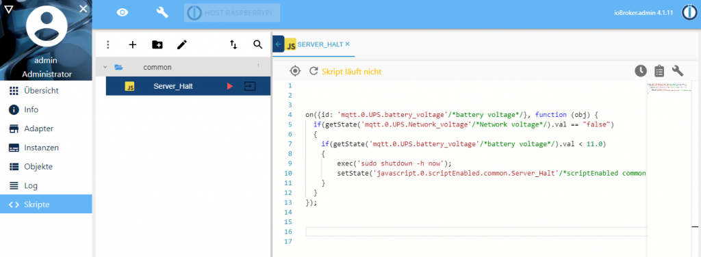
Here we monitor the battery voltage if a change occurs, the function runs. If two conditions are met (If there is no power and the battery voltage drops below 11V), the system is shut down.
What if there is power again?
This method works when the PC is connected to the network with a LAN cable. Check if your machine is suitable for Wake on Lan (WoL). Probably yes.
If everything is OK, build the hardware:

We also need an old mobile charger, plug it in and it’s done.
Or you can connect a 3.3V power supply directly to the ESP8266-01. For example:

Enter the connection information and server MAC address and upload the code below for ESP8266-01 using Arduino.
/**************************************/
//                                    //
//  https://myhomethings.eu           //
//                                    //
//  Generic ESP8266 module            //
//  Flash size: 1M (no SPIFFS)        //
//                                    //
/**************************************/

#include <ESP8266WiFi.h>
#include <WiFiUdp.h>
#include <WiFiClient.h>
#include <WakeOnLan.h>

const char* ssid     = "SSID";
const char* password = "Password";
const char* MACAddress = "xx:xx:xx:xx:xx:xx";

WiFiUDP UDP;
WiFiClient client;
WakeOnLan WOL(UDP);

void setup_wifi()
{
  WiFi.mode(WIFI_STA);
  WiFi.begin(ssid, password);

  while (WiFi.status() != WL_CONNECTED)
  {
    delay(500);
  }
  randomSeed(micros());
}

void setup()
{
  setup_wifi();
  delay(300000);

  WOL.setRepeat(3, 100);
  WOL.calculateBroadcastAddress(WiFi.localIP(), WiFi.subnetMask());
  WOL.sendMagicPacket(MACAddress);
}

void loop()
{
  delay(1000);
  ESP.deepSleep(0);
}
Connect to the socket to which your server is connected.


