Depending on the operating mode, the ESP32 consumes a relatively large amount of energy. When powered from a wall outlet, energy consumption is not a major issue. However, when operating from a battery, it is important to conserve energy in order to maximize the life of the power source.
The ESP32 chip contains a dual-core 32-bit microprocessor with built-in WiFi and Bluetooth support, which makes it an even more power-hungry microcontroller.
If the ESP32 project does not need to be continuously active, a good solution may be to use one of the ESP32’s sleep modes to reduce energy consumption and significantly increase battery life.
advertisement




The advertisements appearing on this site help to maintain it.
Thanks to its advanced power management, the ESP32 offers five configurable power management modes. Depending on the power requirements of the application, you can choose between five different power management modes. You can even switch between modes while the program is running.
The ESP32 has the following operating modes:


SparkFun ESP32 WROOM with ESP32-D0WDQ6 chip
Xtensa dual-core 32-bit LX6 microprocessor Up to 240MHz clock frequency, Integrated 802.11 BGN WiFi, 21 GPIO 8-electrode capacitive touch support
advertising
ESP32 active mode
The active mode of the ESP32 is the normal operating mode, in which the CPU cores are running, the WiFi and Bluetooth modules are enabled, and all peripherals are active.
Block diagram of the ESP32 chip in active mode:
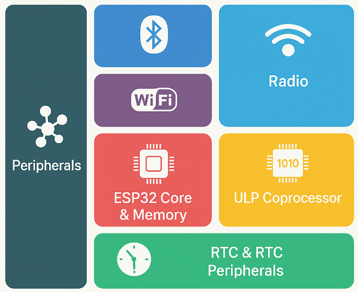
Since everything is active in this mode, the ESP32’s current consumption is 95~240mA depending on WiFi and Bluetooth usage and CPU clock speed. It is important to note that this power consumption value refers to the ESP32 chip and not the entire ESP32 development board.
In active mode, the only way to save energy is to adjust the CPU clock speed and/or change the RF mode according to the application requirements and the following table.
| Power consumption depending on RF modes | |
|---|---|
| Transmit 802.11b, DSSS 1 Mbps, POUT = +19.5 dBm | 240 mA |
| Transmit 802.11g, OFDM 54 Mbps, POUT = +16 dBm | 190 mA |
| Transmit 802.11n, OFDM MCS7, POUT = +14 dBm | 180 mA |
| Receive 802.11b/g/n | 95 ~ 100 mA |
| Transmit BT/BLE, POUT = 0 dBm | 130 mA |
| Receive BT/BLE | 95 ~ 100 mA |
Setting the WiFi radio frequency power level:
#include "esp_wifi.h"
...
// esp_wifi_set_max_tx_power(int level);
esp_wifi_set_max_tx_power(14);        // +14 dBm
Setting the power level of a classic Bluetooth transmitter:
#include "esp_bt.h"
....

// esp_err_t  esp_bredr_tx_power_set(esp_power_level_t  min_power_level, esp_power_level_t  max_power_level);
esp_bredr_tx_power_set(ESP_PWR_LVL_N6, ESP_PWR_LVL_N0);
The default minimum power level is ‘ESP_PWR_LVL_N0’ and the maximum power level is ‘ESP_PWR_LVL_P3’.
The following table lists the possible power level parameters:
| Bluetooth power levels: | |
|---|---|
| ESP_PWR_LVL_N12 | -12dbm |
| ESP_PWR_LVL_N9 | -9dbm |
| ESP_PWR_LVL_N6 | -6dbm |
| ESP_PWR_LVL_N3 | -3dbm |
| ESP_PWR_LVL_N0 | 0dbm |
| ESP_PWR_LVL_P3 | +3dbm |
| ESP_PWR_LVL_P6 | +6dbm |
| ESP_PWR_LVL_P9 | +9dbm |
| ESP_PWR_LVL_N14 = ESP_PWR_LVL_N12 | Backward compatibility! If you set it to -14 dBm, it actually results in -12 dBm. |
| ESP_PWR_LVL_N11 = ESP_PWR_LVL_N9 | Backward compatibility! If you set it to -11 dBm, it actually results in -9 dBm. |
| ESP_PWR_LVL_N8 = ESP_PWR_LVL_N6 | Backward compatibility! If you set it to -8 dBm, it actually results in -6 dBm. |
| ESP_PWR_LVL_N5 = ESP_PWR_LVL_N3 | Backward compatibility! If you set it to -5 dBm, it actually results in -3 dBm. |
| ESP_PWR_LVL_N2 = ESP_PWR_LVL_N0 | Backward compatibility! If you set it to -2 dBm, it actually results in 0 dBm. |
| ESP_PWR_LVL_P1 = ESP_PWR_LVL_P3 | Backward compatibility! If you set it to +1 dBm, it actually results in +3 dBm. |
| ESP_PWR_LVL_P4 = ESP_PWR_LVL_P6 | Backward compatibility! If you set it to +4 dBm, it actually results in +6 dBm. |
| ESP_PWR_LVL_P7 = ESP_PWR_LVL_P9 | Backward compatibility! If you set it to +7 dBm, it actually results in +9 dBm. |
BLE transmit power setting:
#include "esp_bt.h"
....

// esp_err_t esp_ble_tx_power_set(esp_ble_power_type_t power_type, esp_power_level_t power_level)
esp_ble_tx_power_set(ESP_BLE_PWR_TYPE_ADV, ESP_PWR_LVL_P6);
The following table shows the BLE power type parameters:
| BLE power types | |
|---|---|
| ESP_BLE_PWR_TYPE_CONN_HDL0 | TX power for operator 0 |
| ESP_BLE_PWR_TYPE_CONN_HDL1 | TX power for operator 1 |
| ESP_BLE_PWR_TYPE_CONN_HDL2 | TX power for operator 2 |
| ESP_BLE_PWR_TYPE_CONN_HDL3 | TX power for operator 3 |
| ESP_BLE_PWR_TYPE_CONN_HDL4 | TX power for operator 4 |
| ESP_BLE_PWR_TYPE_CONN_HDL5 | TX power for operator 5 |
| ESP_BLE_PWR_TYPE_CONN_HDL6 | TX power for operator 6 |
| ESP_BLE_PWR_TYPE_CONN_HDL7 | TX power for operator 7 |
| ESP_BLE_PWR_TYPE_CONN_HDL8 | TX power for operator 8 |
| ESP_BLE_PWR_TYPE_ADV | TX power for advertising. |
| ESP_BLE_PWR_TYPE_SCAN | TX power for scanning. |
| ESP_BLE_PWR_TYPE_DEFAULT | Default TX power type, which can be used to set the TX power for previously unset power types. |
| ESP_BLE_PWR_TYPE_NUM | Number of types. |
This mode undoubtedly consumes the most power and is the least energy efficient. To save energy, switch to another energy-saving mode.

Modem sleep mode
In modem sleep mode, the ESP32 processor cores and all other peripherals operate at a configurable clock speed, while the radio, Wi-Fi, and Bluetooth are disabled.
Block diagram of the ESP32 in modem sleep mode:

The ESP32 can activate light sleep mode or deep sleep mode with a single command, but activating modem sleep mode is not necessarily that simple. It may require several operations to implement.
If the modem sleep mode is enabled, the Wi-Fi module (in station mode only) will regularly switch between active and sleep modes after successfully connecting to the access point. Bluetooth will also switch between active and sleep modes.
The ESP32 modem can maintain the connection with the access point in sleep mode using DTIM (Delivery Traffic Indication Message). The basic idea behind DTIM is based on beacon technology. It periodically sends messages over the network, notifying all stations to wake up from sleep mode, synchronize themselves on the network, and then go back to sleep. This saves energy.
The Wi-Fi module is disabled between two DTIM beacons and is automatically enabled again when the next beacon arrives. So, the time between two DTIM beacons determines the sleep time of the ESP32 modem.


Modem sleep mode has three possible settings.
Minimal modem sleep.
When modem sleep mode is enabled, received Wi-Fi data is transferred after the DTIM period, so the transmitted data is not lost. The problem is that if there is a lot of traffic on our network, we may receive many beacon messages.
We don’t need to do anything to use it, as this is the default setting for the Wi-Fi modem, but it is necessary if we have previously changed the modem mode. To reset, use the ‘setSleep()’ function in the ‘Wifi.h’ library.
#include <Wifi.h>
....

WiFi.setSleep(true);
For the energy saving settings of the WiFi modem, we can also use the low-level instructions of the ESP-IDF framework in our code. To do this, we need to import the ‘esp_wifi.h’ library so that we can use the ‘esp_wifi_set_ps()’ function. We use it as follows:
#include <esp_wifi.h>
....
esp_wifi_set_ps(WIFI_PS_MIN_MODEM);
Maximum modem sleep.
When the modem’s maximum sleep mode is enabled, communication is checked at regular intervals rather than when beacon messages arrive. In the case of high network traffic, energy consumption may improve slightly, but the transmitted data may be lost because the Wi-Fi module may be in sleep mode during DTIM.
Since the ‘Wifi.h’ library does not contain instructions for this, we need to use the low-level function of the ESP-IDF framework to enable maximum modem sleep mode, so we need to import the ‘esp_wifi.h’ library to use the ‘esp_wifi_set_ps(WIFI_PS_MAX_MODEM)’ function.
#include <esp_wifi.h>
....

esp_wifi_set_ps(WIFI_PS_MAX_MODEM);
Disable modem sleep mode.
This mode completely disables the modem’s sleep mode. This results in much higher power consumption, but ensures minimal delay for real-time data reception over the Wi-Fi network.
Here, we can also use the ‘setSleep()’ function from the ‘Wifi.h’ library.
#include <Wifi.h>
....

WiFi.setSleep(false);
Or import the ‘esp_wifi.h’ library to use the ‘esp_wifi_set_ps(WIFI_PS_NONE )’ function.
#include <esp_wifi.h>
....

esp_wifi_set_ps(WIFI_PS_NONE);
Disabling the elements of the radio group.
It is quite unclear what is required to implement modem sleep mode. Some say that disabling the entire radio group is necessary, while others say that the minimum sleep mode of the Wi-Fi modem (which is the default mode) is sufficient.
In any case, to achieve further energy savings, we can turn off the Bluetooth radio when not in use.
btStop();If we don’t need Wi-Fi, we can disable it. First, we turn off Wi-Fi with the ‘WiFi.disconnect(true);’ function, then we disable the Wi-Fi modem with the ‘WiFi.mode(WIFI_OFF);’ function.
#include <Wifi.h>
...

WiFi.disconnect(true);
WiFi.mode(WIFI_OFF);
This does not significantly change the average energy consumption, but it does not respond to DTIM beacon messages, so the surge in power consumption when receiving WiFi data is eliminated. This also saves a few mA.
To reset WiFi, the following functions must be performed:
#include <Wifi.h>
...

WiFi.disconnect(false);
WiFi.mode(WIFI_STA);
WiFi.begin(STA_SSID, STA_PASS);
while (WiFi.status() != WL_CONNECTED)
{
  delay(500);
}
Let’s reduce the CPU clock frequency.
Power consumption depends significantly on the CPU clock speed. In this mode, better results can be achieved by reducing the CPU clock speed. Reducing the clock speed reduces power consumption, while increasing the clock speed increases energy consumption.
The table below shows energy consumption as a function of CPU clock speed.
| CPU frequency | Energy consumption |
|---|---|
| 240 MHz | 30 mA ~ 68 mA |
| 160 MHz | 27 mA ~ 44 mA |
| 80 MHz | 20 mA ~ 31 mA |
There is a function for setting the CPU frequency, which is ‘setCpuFrequencyMhz(80)’.
setCpuFrequencyMhz(80);And there is a function for querying the CPU frequency, ‘getCpuFrequencyMhz()’.
Serial.println(getCpuFrequencyMhz());void setup()
{
Serial.begin(115200);
delay(2000);
Serial.print("basic frequency: ");
Serial.println(getCpuFrequencyMhz());
delay(1000);
setCpuFrequencyMhz(80);
delay(2000);
Serial.print("1. modified frequency: ");
Serial.println(getCpuFrequencyMhz());
setCpuFrequencyMhz(40);
delay(2000);
Serial.print("2. modified frequency: ");
Serial.println(getCpuFrequencyMhz());
}
void loop(){}


Light sleep mode
In light sleep mode, the ESP32’s Wi-Fi and Bluetooth radios do not work, the CPU is suspended (it operates clock-controlled), and most of the RAM and digital peripherals are shut down.
The block diagram of the ESP32 in light sleep mode looks like this:
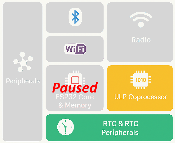
Switching to easy sleep mode may not work if there is active Wi-Fi or Bluetooth data traffic. It may be worth disconnecting before doing so.
btStop();
WiFi.disconnect(true);
WiFi.mode(WIFI_OFF);
The ESP32’s light sleep mode can be activated with the following function.
esp_light_sleep_start();Before activating light sleep mode, we must specify the system wake-up mode, then we can start light sleep mode.
If we enter sleep mode without configuring wake-up sources, the chip will remain in sleep mode indefinitely until we perform an external reset.
When exiting light sleep mode, the CPU resumes operation where it left off, and the status of peripherals and variable values are preserved.
The ESP32 chip can be awakened from light sleep mode as described in the section on wake up sources.


Deep sleep mode
In ESP32 deep sleep mode, the CPU cores, a significant portion of the RAM, and all digital peripherals controlled by the Advanced Peripheral Bus (APB_CLK) clock are turned off. However, the real-time clock (RTC) controller, the Ultra Low Power (ULP) coprocessor, the RTC peripherals, and the RTC memories remain available.
Block diagram of the ESP32 in deep sleep mode:

Before activating the ESP32 deep sleep mode, we need to specify the system wake-up mode.
If we enter sleep mode without specifying wake-up sources, the esp32 will remain in sleep mode until we perform an external reset.
Deep sleep mode can be activated with the following function:
esp_deep_sleep_start();Every time the ESP32 wakes up from deep sleep, it performs a full reboot instead of continuing where it left off.
If we need to store any data and retrieve it after waking up from deep sleep, we must save it to the RTC memory. The data stored here is not lost in deep sleep mode, but it is deleted when the reset button is pressed.
RTC_DATA_ATTR int myData = 0;You can return from deep sleep mode using one of the methods described in the section on wake sources.
Shelly Flood

Wireless Flood Sensor with Temperature Measurement, Dripping & Leaking Alarm, Floor Heating Control, Compact Design, Easy to Use, Battery Life up to 18 Months
advertising – amazon.com
Hibernation mode
The ESP32’s hibernation state is actually an extended deep sleep mode designed to minimize power consumption to the lowest possible level. This state is achieved by turning off virtually all non-essential units.
In ESP32 hibernation mode, all oscillators, the RTC peripheral range and RTC memories, as well as the Ultra Low Power (ULP) coprocessor are disabled.
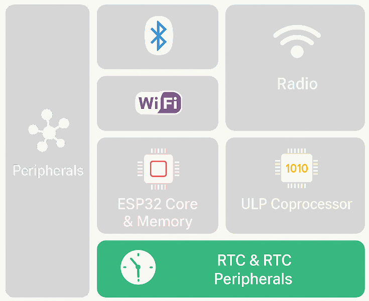
In hibernation mode, only one RTC timer is available at a slow clock speed, and only certain RTC GPIO pins are active, which are necessary for waking up from hibernation. This allows us to achieve the lowest possible power consumption of up to 5 µA.
The ‘esp_sleep_pd_config()’ function helps manage the ESP32 chip’s power ranges.
esp_sleep_pd_config(domain, option);| Power range domain | |
|---|---|
| ESP_PD_DOMAIN_RTC_PERIPH | RTC peripherals |
| ESP_PD_DOMAIN_RTC_FAST_MEM | RTC fast memory (ULP programs). |
| ESP_PD_DOMAIN_RTC_SLOW_MEM | RTC slow memory (ULP data). |
| ESP_PD_DOMAIN_XTAL | crystal oscillator |
| Options for domains | |
|---|---|
| ESP_PD_OPTION_OFF | Turns off the specified domain |
| ESP_PD_OPTION_ON | Turns on the specified domain |
esp_sleep_pd_config(ESP_PD_DOMAIN_RTC_PERIPH, ESP_PD_OPTION_OFF);
esp_sleep_pd_config(ESP_PD_DOMAIN_RTC_FAST_MEM, ESP_PD_OPTION_OFF);
esp_sleep_pd_config(ESP_PD_DOMAIN_RTC_SLOW_MEM, ESP_PD_OPTION_OFF);
esp_sleep_pd_config(ESP_PD_DOMAIN_XTAL, ESP_PD_OPTION_OFF);
Then we can activate hibernation mode.
esp_deep_sleep_start();Since the RTC memory is also turned off, no data can be retained in hibernation mode. In this case, the only way to save data is to write it to the EEPROM.
#include <EEPROM.h>
int myData = 1;

void setup()
{
  EEPROM.begin(1);
}
void loop()
{
  myData = 5;
  EEPROM.write(0, myData);
  EEPROM.commit();
}


advertising – Amazon.com
Wake sources and examples
Timer wake-up
The RTC timer can be set using the esp_sleep_enable_timer_wakeup() function to wake up the ESP32 from light/deep sleep mode at specified intervals. The following example wakes up the ESP32 after 5 seconds.
esp_sleep_enable_timer_wakeup(5 * 1000000);   // 5 sec
esp_light_sleep_start();
Let’s look at an example of returning from light sleep.
byte ledPin = 4;

void setup()
{
  Serial.begin(115200);
  delay(50);
  Serial.println("starting...");

  pinMode(ledPin, OUTPUT);
  digitalWrite(ledPin, LOW);
  delay(2000);
  digitalWrite(ledPin, HIGH);
  delay(2000);

  Serial.println("go to light sleep...");
  delay(50);
  esp_sleep_enable_timer_wakeup(5 * 1000000);   // 5 sec
  esp_light_sleep_start();

  Serial.println("hi again here!");
}

void loop(){}
As we can see, after waking up from light sleep, the esp32 continues running the program where it left off, so the greeting “hi again here!” appears on the serial monitor and the connected LED stays on.
Let’s see what happens to our program when we send the esp32 into deep sleep.
byte ledPin = 4;

void setup()
{
  Serial.begin(115200);
  delay(50);
  Serial.println("starting...");

  pinMode(ledPin, OUTPUT);
  digitalWrite(ledPin, LOW);
  delay(2000);
  digitalWrite(ledPin, HIGH);
  delay(2000);

  Serial.println("go to deep sleep...");
  delay(50);
  esp_sleep_enable_timer_wakeup(5 * 1000000);   // 5 sec
  esp_deep_sleep_start();

  Serial.println("you never see this: hi again here!");
}

void loop(){}
In this case, the esp32 restarts after waking up. The inputs and outputs are reinitialized and do not retain their previous state. The program lines following the “esp_deep_sleep_start()” function are never executed.
Waking up due to an external event (e.g., pressing a button) is another way to wake up the ESP32. There are two options for external wake-up: ext0 and ext1.
External wake-up (ext0)
The ESP32 has 16 RTC GPIOs that are part of the RTC Low-Power subsystem. These RTC GPIOs can wake up the ESP32 from an external source when the Ultra Low Power (ULP) coprocessor is running.
Ext0 wakeup means that we can wake up the ESP32 from sleep by pressing a button connected to an RTC GPIO.
To use the ESP32 wakeup source, we can use the following function:
esp_sleep_enable_ext0_wakeup(GPIO_pin_num, level);The first argument of the function is the GPIO number of the pin to be used. The second parameter indicates the state of the GPIO that triggers the wake-up. This can be 1 or 0.
The dedicated pins of the RTC GPIO are shown in the following figure:
| RTC_GPIO0 | GPIO36 |
| RTC_GPIO3 | GPIO39 |
| RTC_GPIO4 | GPIO34 |
| RTC_GPIO5 | GPIO35 |
| RTC_GPIO6 | GPIO25 |
| RTC_GPIO7 | GPIO26 |
| RTC_GPIO8 | GPIO33 |
| RTC_GPIO9 | GPIO32 |
| RTC_GPIO10 | GPIO4 |
| RTC_GPIO11 | GPIO0 |
| RTC_GPIO12 | GPIO2 |
| RTC_GPIO13 | GPIO15 |
| RTC_GPIO14 | GPIO13 |
| RTC_GPIO15 | GPIO12 |
| RTC_GPIO16 | GPIO14 |
| RTC_GPIO17 | GPIO27 |
The following image shows the RTC_GPIO pins on the ESP32 38-pin development board:

Example of waking up esp32 from deep sleep by pressing a button.
const gpio_num_t ledPin = GPIO_NUM_4;
const gpio_num_t wakePin = GPIO_NUM_0;
int wakeLevel = 0;

void setup()
{
  Serial.begin(115200);
  delay(50);
  Serial.println("starting...");

  pinMode(ledPin, OUTPUT);
  digitalWrite(ledPin, LOW);
  delay(2000);
  digitalWrite(ledPin, HIGH);
  delay(2000);

  Serial.println("go to deep sleep...");
  delay(50);
  esp_sleep_enable_ext0_wakeup(wakePin, wakeLevel);
  esp_deep_sleep_start();

  Serial.println("you never see this");
}
void loop(){}
This alarm mode also works for light sleepers:
const gpio_num_t ledPin = GPIO_NUM_4;
const gpio_num_t wakePin = GPIO_NUM_0;
int wakeLevel = 0;

void setup()
{
  Serial.begin(115200);
  delay(50);
  Serial.println("starting...");

  pinMode(ledPin, OUTPUT);
  digitalWrite(ledPin, LOW);
  delay(2000);
  digitalWrite(ledPin, HIGH);
  delay(2000);

  Serial.println("go to light sleep...");
  delay(50);
  esp_sleep_enable_ext0_wakeup(wakePin, wakeLevel);
  esp_light_sleep_start();

  Serial.println("hi again here!");
}
void loop(){}
Smart Remote – IR Blaster, Link SwitchBot to Wi-Fi (Support 2.4GHz), Control TV, Air Conditioner, Compatible with Alexa, Google Home, IFTTT

Work as a WiFi Thermometer Hygrometer, IR Remote Control, Smart Remote and Light Sensor, Link SwitchBot to Wi-Fi (Support 2.4GHz), Compatible with Alexa&Google Assistant
advertising
External wake-up (ext1)
The ext1 wake source allows simultaneous use of multiple RTC GPIOs. To use the ext1 wake source, we need to use the following function:
esp_sleep_enable_ext1_wakeup_io(bitmask, mode);This function accepts two arguments:
The first argument is a bitmask of GPIO numbers that participate in the wakeup.
The second, the ‘mode’ parameter, determines the logic that triggers the wakeup.
| The logic behind waking up | |
|---|---|
| ESP_EXT1_WAKEUP_ALL_LOW | Wakes up when all enabled GPIO pins goes low. |
| ESP_EXT1_WAKEUP_ANY_HIGH | Wakes up when any enabled GPIO goes high. |
An example of waking up from light sleep with ext1.
#include "driver/rtc_io.h"

const gpio_num_t ledPin = GPIO_NUM_4;
const gpio_num_t wakePin1 = GPIO_NUM_12;
const gpio_num_t wakePin2 = GPIO_NUM_14;
const gpio_num_t wakePin3 = GPIO_NUM_27;

// Macro for GPIO bitmask
#define WAKE_PIN_BITMASK(GPIO) (1ULL << GPIO)

// Creating a bitmask
uint64_t bitmask = WAKE_PIN_BITMASK(wakePin1) | WAKE_PIN_BITMASK(wakePin2) | WAKE_PIN_BITMASK(wakePin3);

// function to print the GPIO that triggered the wake-up
void print_GPIO_wake_up()
{
  uint64_t GPIO_reason = esp_sleep_get_ext1_wakeup_status();
  Serial.print("The pin that triggers the wake-up: ");
  Serial.println((log(GPIO_reason))/log(2), 0);
}
void setup()
{
  Serial.begin(115200);
  delay(50);
  Serial.println("starting...");

  pinMode(ledPin, OUTPUT);
  digitalWrite(ledPin, LOW);
  delay(2000);
  digitalWrite(ledPin, HIGH);
  delay(2000);

  // activate pull-down resistor
  pinMode(wakePin1, INPUT_PULLDOWN);
  pinMode(wakePin2, INPUT_PULLDOWN);
  pinMode(wakePin3, INPUT_PULLDOWN);

  // Configuring the wakeup pin(s) as RTC IO for EXT1 wakeup
  rtc_gpio_deinit(wakePin1);
  rtc_gpio_deinit(wakePin2);
  rtc_gpio_deinit(wakePin3);

  // Enable EXT1 wake source
  esp_sleep_enable_ext1_wakeup(bitmask, ESP_EXT1_WAKEUP_ANY_HIGH);
}

void loop()
{
  Serial.println("Enter light sleep mode...");
  delay(100);
  // Enter light sleep mode
  esp_light_sleep_start();

  // After wake-up, disable the hold function on the RTC GPIOs.
  rtc_gpio_hold_dis(wakePin1);
  rtc_gpio_hold_dis(wakePin2);
  rtc_gpio_hold_dis(wakePin3);

  Serial.println("Entering light sleep mode...");
  // We print the GPIO number that caused the wake-up
  print_GPIO_wake_up();

  delay(2000);
}
And another ext1 wake-up call from deep sleep.
#include "driver/rtc_io.h"

const gpio_num_t ledPin = GPIO_NUM_4;
const gpio_num_t wakePin1 = GPIO_NUM_12;
const gpio_num_t wakePin2 = GPIO_NUM_14;
const gpio_num_t wakePin3 = GPIO_NUM_27;

// Macro for GPIO bitmask
#define WAKE_PIN_BITMASK(GPIO) (1ULL << GPIO)

// Creating a bitmask
uint64_t bitmask = WAKE_PIN_BITMASK(wakePin1) | WAKE_PIN_BITMASK(wakePin2) | WAKE_PIN_BITMASK(wakePin3);

// function to print the GPIO that triggered the wake-up
void print_GPIO_wake_up()
{
  uint64_t GPIO_reason = esp_sleep_get_ext1_wakeup_status();
  if(GPIO_reason != 0)
  {
    Serial.print("The pin that triggers the wake-up: ");
    Serial.println((log(GPIO_reason))/log(2), 0);
  }
}
void setup()
{
  Serial.begin(115200);
  delay(50);
  Serial.println("starting...");

  pinMode(ledPin, OUTPUT);
  digitalWrite(ledPin, LOW);
  delay(2000);
  digitalWrite(ledPin, HIGH);
  delay(2000);

  // activate pull-down resistor
  pinMode(wakePin1, INPUT_PULLDOWN);
  pinMode(wakePin2, INPUT_PULLDOWN);
  pinMode(wakePin3, INPUT_PULLDOWN);

  // Configuring the wakeup pin(s) as RTC IO for EXT1 wakeup
  rtc_gpio_deinit(wakePin1);
  rtc_gpio_deinit(wakePin2);
  rtc_gpio_deinit(wakePin3);

  // Enable EXT1 wake source
  esp_sleep_enable_ext1_wakeup(bitmask, ESP_EXT1_WAKEUP_ANY_HIGH);
}

void loop()
{
  rtc_gpio_hold_dis(wakePin1);
  rtc_gpio_hold_dis(wakePin2);
  rtc_gpio_hold_dis(wakePin3);

  print_GPIO_wake_up();

  Serial.println("Entering deep sleep mode...");
  delay(100);
  esp_deep_sleep_start();
}
Touchpad wake-up
The ESP32 panel has 10 capacitive touchscreen GPIOs (which may vary depending on the ESP32 chip). These GPIOs are capable of detecting changes in objects containing electrical charge, such as human skin. This allows them to detect changes when the GPIOs are touched with a finger. These ESP32 touch pins can be used to wake the ESP32 from deep sleep.
The RTC IO module contains the logic for handling wake-up triggered by the touch sensor. To wake up using the touch sensor, we need to configure the touchpad interrupt before the ESP32 enters deep or light sleep mode.
The touch sensor wake-up source can be enabled using the ‘esp_sleep_enable_touchpad_wakeup()’ function.
touchSleepWakeUpEnable(TOUCH_PIN, THRESHOLD);The ‘esp_sleep_get_touchpad_wakeup_status()’ function returns which touchpad pin triggered the wakeup.
touch_pad_t touchPin = esp_sleep_get_touchpad_wakeup_status();The ESP32 touch sensors are connected to these dedicated GPIO pins.
| Touch0 | GPIO4 |
| Touch1 | GPIO0 |
| Touch2 | GPIO2 |
| Touch3 | GPIO15 |
| Touch4 | GPIO13 |
| Touch5 | GPIO12 |
| Touch6 | GPIO14 |
| Touch7 | GPIO27 |
| Touch8 | GPIO33 |
| Touch9 | GPIO32 |
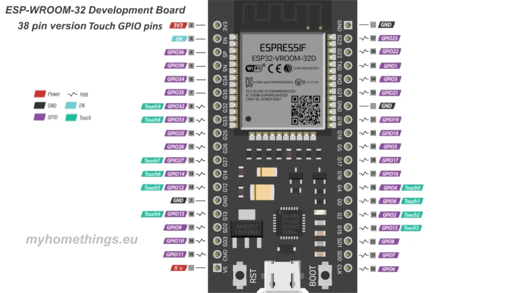
The Arduino IDE includes an easy-to-understand sample code for this under File/Examples/ESP32 Deep Sleep/ in the TouchWakeUp sketch.
Waking up with the ULP coprocessor
The ULP coprocessor can also run in ESP32 sleep mode and execute programs stored in RTC SLOW memory. It can be used to query sensors and ADC values, monitor touch sensors, and wake up the chip when an event is detected, among other things.
Both the CPU and the ULP coprocessor can access the RTC SLOW memory, so it can be used to share data between the CPU and the ULP coprocessor.
You can read more about programming the ULP coprocessor at the following link:
https://docs.espressif.com/projects/esp-idf/en/v5.4.2/esp32/api-reference/system/ulp.html#
Meross Smart WiFi Table Lamp
Bedside Lamp, Compatible with Apple HomeKit, Siri, Amazon Alexa, Google Assistant and SmartThings, Tunable White and Multi-Color, Touch Control, Voice and APP Control
advertising – amazon.com

Reasons for waking up
We often need to know what woke the ESP32 from sleep mode and under what conditions our program should continue running. The ‘esp_sleep_get_wakeup_cause()’ function returns what triggered the wake-up.
wakeup_reason = esp_sleep_get_wakeup_cause();

  switch(wakeup_reason)
  {
  case ESP_SLEEP_WAKEUP_EXT0 :
    Serial.println("External source-triggered wake-up (ext0)");
    break;
  case ESP_SLEEP_WAKEUP_EXT1 :
    Serial.println("External source-triggered wake-up (ext1)");
    break;
  case ESP_SLEEP_WAKEUP_TIMER :
    Serial.println("Timer triggered wake-up");
    break;
  case ESP_SLEEP_WAKEUP_TOUCHPAD :
    Serial.println("Touchpad-activated wake-up");
    break;
  case ESP_SLEEP_WAKEUP_ULP :
    Serial.println("ULP program-triggered wake-up");
    break;
  default :
    Serial.printf("Undefined source: %d\n", wakeup_reason);
    break;
  }
}
#include "driver/rtc_io.h"
const gpio_num_t ledPin = GPIO_NUM_4;
const gpio_num_t wakePin1 = GPIO_NUM_12;
const gpio_num_t wakePin2 = GPIO_NUM_14;
const gpio_num_t wakePin3 = GPIO_NUM_27;
const gpio_num_t wakePin = GPIO_NUM_0;
int wakeLevel = 0;
// Macro for GPIO bitmask
#define WAKE_PIN_BITMASK(GPIO) (1ULL << GPIO)
// Creating a bitmask
uint64_t bitmask = WAKE_PIN_BITMASK(wakePin1) | WAKE_PIN_BITMASK(wakePin2) | WAKE_PIN_BITMASK(wakePin3);
// function to print the GPIO that triggered the wake-up
void print_GPIO_wake_up()
{
uint64_t GPIO_reason = esp_sleep_get_ext1_wakeup_status();
if(GPIO_reason != 0)
{
Serial.print("The pin that triggers the wake-up: ");
Serial.println((log(GPIO_reason))/log(2), 0);
}
}
// function for printing the reason for waking up
void print_wakeup_reason()
{
esp_sleep_wakeup_cause_t wakeup_reason;
wakeup_reason = esp_sleep_get_wakeup_cause();
switch(wakeup_reason)
{
case ESP_SLEEP_WAKEUP_EXT0 :
Serial.println("External source-triggered wake-up (ext0)");
break;
case ESP_SLEEP_WAKEUP_EXT1 :
Serial.println("External source-triggered wake-up (ext1)");
break;
case ESP_SLEEP_WAKEUP_TIMER :
Serial.println("Timer triggered wake-up");
break;
case ESP_SLEEP_WAKEUP_TOUCHPAD :
Serial.println("Touchpad-activated wake-up");
break;
case ESP_SLEEP_WAKEUP_ULP :
Serial.println("ULP program-triggered wake-up");
break;
default :
Serial.printf("Undefined source: %d\n", wakeup_reason);
break;
}
}
void setup()
{
Serial.begin(115200);
delay(50);
Serial.println("starting...");
pinMode(ledPin, OUTPUT);
digitalWrite(ledPin, LOW);
delay(2000);
digitalWrite(ledPin, HIGH);
delay(2000);
// activate pull-down resistor
pinMode(wakePin1, INPUT_PULLDOWN);
pinMode(wakePin2, INPUT_PULLDOWN);
pinMode(wakePin3, INPUT_PULLDOWN);
// Configuring the wakeup pin(s) as RTC IO for EXT1 wakeup
rtc_gpio_deinit(wakePin1);
rtc_gpio_deinit(wakePin2);
rtc_gpio_deinit(wakePin3);
// Enable EXT0 wake source
esp_sleep_enable_ext0_wakeup(wakePin, wakeLevel);
// Enable EXT1 wake source
esp_sleep_enable_ext1_wakeup(bitmask, ESP_EXT1_WAKEUP_ANY_HIGH);
// Enable RTC timer wake source
esp_sleep_enable_timer_wakeup(15 * 1000000);
}
void loop()
{
rtc_gpio_hold_dis(wakePin1);
rtc_gpio_hold_dis(wakePin2);
rtc_gpio_hold_dis(wakePin3);
print_wakeup_reason();
print_GPIO_wake_up();
Serial.println("Entering light sleep mode...");
delay(1000);
esp_light_sleep_start();
}